English
 Drawing Review
Review the 2D drawing, 3D model, alloy, side features, critical dimensions, finish, annual volume and inspection requirements.
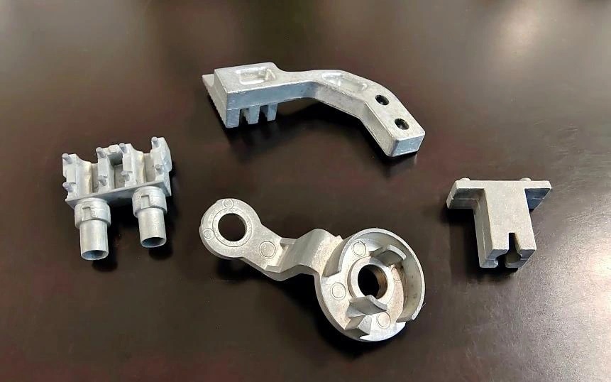
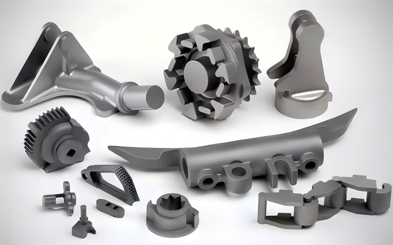
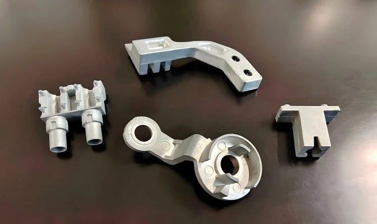
Multi-slide die casting is a high-pressure zinc casting process that uses multiple independently moving tool slides to form a component from several directions. It is commonly selected for small parts with complex side features, undercuts and recurring production requirements. Suitable features can be formed directly in the tool, while precision bores, threads and sealing surfaces may still require machining.
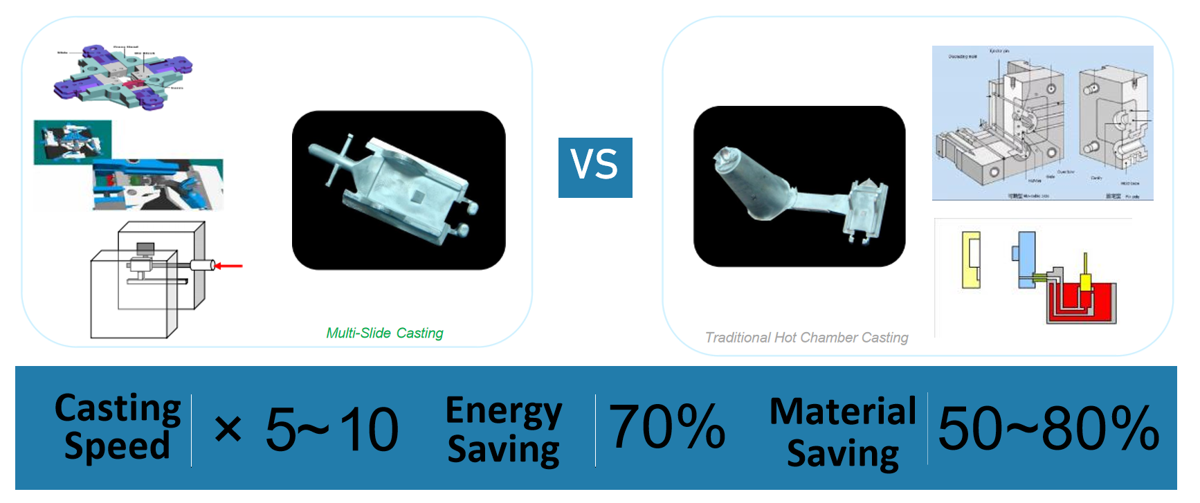
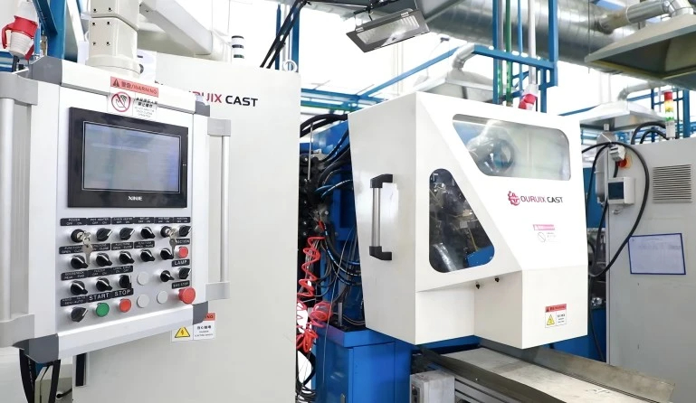
Equipment and tooling are selected according to the part envelope, projected area, alloy, wall thickness, feature directions, shot requirements and expected production volume. Machine specifications and slide quantity are confirmed separately for each project.
Review the 2D drawing, 3D model, alloy, side features, critical dimensions, finish, annual volume and inspection requirements.
Determine slide directions, release, draft, parting lines, gates, machining, inspection datums and potential defect risks.
Design forming slides, cavity inserts, runner, gates, overflows, vents, trimming and any required fixtures.
Close and lock the slides, inject zinc, hold pressure, cool, retract the slides, remove the part and trim it.
Check filling, flash, slide witness marks, critical dimensions, machining, finish and assembly fit.
Transfer approved tooling settings, inspection points and acceptance standards into controlled recurring production.
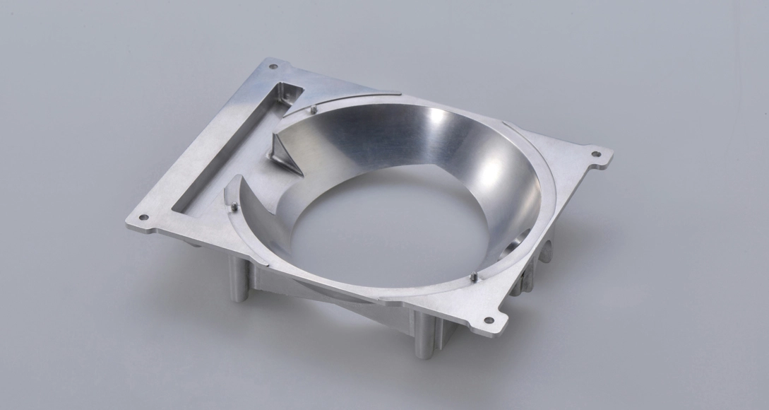
Multi-slide casting is primarily intended for small precision components with several feature directions. The following descriptions are project-evaluation guidance rather than unconditional specifications.
| Capability Item | Capability Description |
|---|---|
| Main Process | Hot-chamber multi-slide zinc die casting |
| Available Alloys | Zamak 3 and Zamak 5; other zinc alloys subject to project review |
| Suitable Part Type | Small and complex components with multiple side features |
| Part Size | Confirmed according to part envelope, projected area and available equipment |
| Part Weight | Confirmed after evaluating component and runner shot requirements |
| Wall Thickness | Thin-wall features are evaluated according to flow length, alloy, area and tooling design |
| Slide Configuration | Multiple independently moving slides; quantity and direction depend on geometry |
| Undercuts | Possible where the feature can be released through a suitable slide direction |
| Critical Tolerance | Evaluated according to feature size, datum, slide direction and inspection method |
| Secondary Machining | May be reduced for suitable features but remains necessary for selected precision surfaces |
| Production Volume | Most appropriate for recurring medium- and high-volume programs |
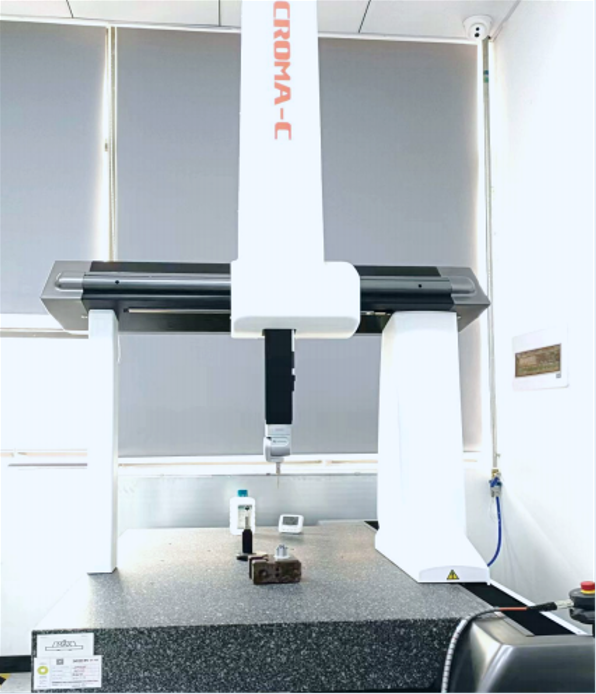
| Inspection | Optical measurement, dimensional measurement, gauges or fixtures selected by feature type |
Neither route is universally better. The correct process is determined by part size, opening directions, side features, machining needs, tooling complexity and repeat volume.
| Comparison Item | Multi-slide Die Casting | Conventional Die Casting |
|---|---|---|
| Suitable Part Size | Primarily small precision components; final range depends on equipment and tooling | Supports a broader range of small and medium-sized parts |
| Part Complexity | Suitable for parts with several side features and undercuts | Suitable for parts based mainly on a conventional opening direction |
| Tool Movement | Multiple independent slides form features from different directions | Main tool opens conventionally, with slides or cores added where necessary |
| Undercuts / Side Features | Can form several side features where travel and release permit | Side actions are possible but may increase conventional tool complexity |
| Secondary Machining | May reduce drilling or milling for selected side features | Depends on part geometry, tolerance and tooling arrangement |
| Tooling Complexity | Affected by slide quantity, inserts, feature directions and target life | Affected by tool size, cavity count, machine capacity and core pulls |
| Tooling Cost | Evaluated by slide quantity, complexity, inserts and expected production life | Evaluated by tool size, cavities, side actions and machine requirements |
| Production Volume | Best suited to recurring medium- and high-volume small parts | Suitable for a broader range of recurring production programs |
| Best-fit Applications | Connectors, lock parts, electronic hardware and small mechanisms | Housings, brackets, handles and general zinc die cast parts |
The following categories describe component types that may benefit from multi-directional tooling. Final suitability is confirmed through drawing and DFM review.
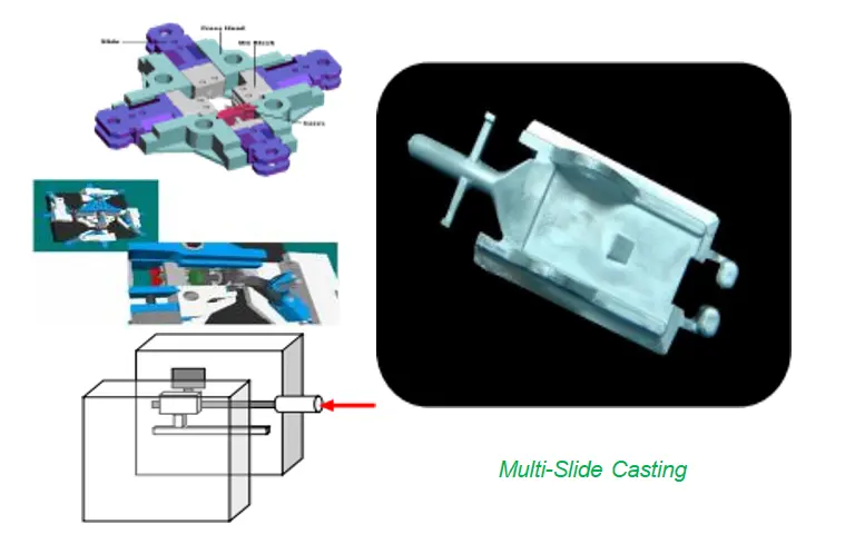
Connector shells, housings, terminal supports, shielding parts, interfaces, switch parts and sensor housings.
Lock cylinders, levers, latches, small lock bodies, key mechanisms and integrated side-hole parts.
Small housings, interface parts, hinges, mounting elements, shielding parts and accessories.
Smart-key mechanisms, connector structures, small locking parts, control components and mechanisms.
Dimensional capability is evaluated according to feature size, datum structure, slide direction, component geometry and inspection method. Tolerance capability is confirmed for each critical feature rather than assigned as one universal value for the complete part.
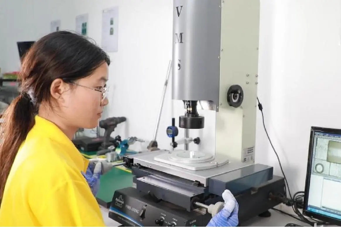
Tight local tolerances may be achievable on selected features under controlled tooling and measurement conditions, but final capability must be confirmed through T1 samples and dimensional inspection.
Tolerance confirmation considers the nominal size, datum, feature direction, as-cast or machined condition, inspection method, sample quantity and acceptance standard.
A feature formed by one cavity section and measured without secondary machining.
A dimension affected by the relationship between independently moving forming sections.
A bore, thread, face or other feature completed after casting and measured as a machined result.
| Evidence Item | Required Evidence |
|---|---|
| Critical Feature | Identify the exact dimension or geometry being controlled |
| Nominal Size | State the feature size rather than presenting tolerance alone |
| Process Condition | As-cast, slide-formed or CNC-machined |
| Inspection Method | Optical measurement, three-dimensional measurement, gauge or fixture |
| Sample Quantity | State the number of T1 or production samples inspected |
| Tooling Condition | Initial T1, approved tooling or production after maintenance |
| Result Type | Individual measurement, tolerance confirmation or capability study |
| Acceptance Standard | Customer drawing, agreed specification or control plan |
Target tooling life is evaluated according to zinc alloy, tool material, cavity design, slide complexity, production rate, maintenance plan and acceptable wear limits.
Replaceable inserts, slides and other wear components may require maintenance or replacement before the complete mold base reaches the end of its service life. The quotation should clarify which part of the tool a target-life statement applies to.
The following is a representative engineering example rather than a disclosed customer project. Actual project details can be reviewed when approved records are available.
Under a conventional tooling concept, the side windows and locating groove could require separate drilling or milling, adding fixtures, handling, dimensional accumulation and risk of cosmetic damage before plating.
Evaluate independent slides for the windows, groove and retention features.
Keep the reference bore as a CNC-machined feature for tighter positional control.
Inspect filling, witness lines, side-feature dimensions, bore position and fit.
Combine casting, local machining, deburring, plating and final verification.
For a suitable component, this approach can reduce selected post-casting drilling or milling while retaining CNC machining only for critical functional features.
Use this checklist to determine whether the drawing contains enough information for a multi-slide feasibility review.
The cost of multi-slide zinc die casting depends on the part structure, tooling complexity, annual volume and required secondary operations. A complete drawing review is necessary before tooling and unit pricing can be confirmed.
Side holes, undercuts, grooves and features facing several directions may require additional slides, inserts or more complex release arrangements, increasing tooling-development requirements.
Tool cost is affected by cavity quantity, replaceable inserts, expected maintenance and target tooling life. Recurring medium- or high-volume production generally provides better tooling economics than short-run projects.
CNC machining, plating, polishing, assembly, dedicated fixtures and dimensional reports add downstream cost. These requirements should be defined during RFQ so Eesson can evaluate the complete production route rather than quote the casting operation alone.


Multi-slide zinc die casting uses independently moving slides to form selected side holes, slots, grooves, windows and undercuts directly in the tooling. For suitable part designs, this can reduce separate drilling, milling or assembly steps and improve consistency across repeat production. However, precision bores, internal threads, sealing surfaces and tight positional features may still require CNC machining. Eesson evaluates the drawing, slide directions, critical dimensions, finishing requirements and annual volume before confirming the most practical production route. The actual reduction in secondary operations depends on the complete component geometry and should be validated through DFM review and T1 sample inspection.
Multi-slide die casting allows for the creation of highly intricate and precise components, achieving tolerances as tight as 0.005mm. This capability is essential for industries requiring detailed and complex parts, such as electronics and automotive sectors.
The multi-slide mechanism enables faster cycle times and higher production rates compared to traditional die casting methods. This efficiency reduces lead times and increases overall throughput, making it ideal for high-volume manufacturing.
The advanced tooling design allows for the production of near-net-shape parts, minimizing the need for additional machining or finishing processes. This reduction in secondary processing not only saves time but also lowers production costs.
Multi-slide die casting tools are designed for durability, with a guaranteed lifespan of 1,000,000 to 1,500,000 shots. This extended tooling life reduces the frequency of replacements and maintenance, leading to lower operational costs and consistent quality over long production runs.
Multi-slide die casting is an advanced manufacturing process that uses multiple sliding tools to create complex and precise metal parts. Unlike traditional die casting, it allows for the creation of intricate geometries and tight tolerances by enabling the die inserts to be withdrawn from multiple angles and directions.
Multi-slide die casting is compatible with a variety of metals, including zinc, aluminum, and magnesium alloys. The choice of material depends on the specific requirements of the part, such as strength, weight, and thermal conductivity.
The multi-slide mechanism allows for faster cycle times and higher production rates. This efficiency is achieved through the simultaneous operation of multiple slides, which reduces the overall time required to produce each part. Additionally, the process minimizes the need for secondary machining, further enhancing production efficiency.
Multi-slide die casting excels in producing highly intricate and precise components with tight tolerances. The ability to withdraw die inserts from multiple angles allows for the creation of complex geometries that would be difficult or impossible to achieve with traditional die casting methods. This makes it ideal for industries such as electronics, automotive, and medical devices.
The tooling used in multi-slide die casting is designed for durability, with a guaranteed lifespan of 1,000,000 to 1,500,000 shots. This extended tooling life reduces the frequency of replacements and maintenance, leading to lower operational costs and consistent quality over long production runs.
While the initial investment in multi-slide die casting equipment and tooling may be higher than traditional methods, the long-term cost benefits are significant. The process reduces the need for secondary machining, lowers material waste, and increases production efficiency. Additionally, the extended tooling life and high-quality output contribute to overall cost savings in high-volume manufacturing.


Room J757, No. 5358, Huyi Rd, Jiading, Shanghai, China
Room J757, No. 5358, Huyi Rd, Jiading, Shanghai, China